Posted 13 March 2018
In a recent post, I described my study of the widely available and dirt-cheap TP5100 1/2-cell LiPo battery charger as a possible replacement for my current Adafruit PB1000C-based battery charger. Based on the results of this study, it was clear the TP5100-based system was superior in all respects to my home-brew system:
- Twice the charge current (2A vs 1A) means significantly shortened charge times
- Much smaller and simpler
- Charger current path independent of load path – much lower IR drop
- Battery always connected to the system, so no requirement for ultra-low-drop MOSFET diode
- Much simpler software – no requirement to monitor status of two separate chargers
- No electromechanical relay to screw up.
I constructed a small charger module using some perfboard and a couple of 2-place screw terminals, as shown below (with the previous module shown for size comparison).
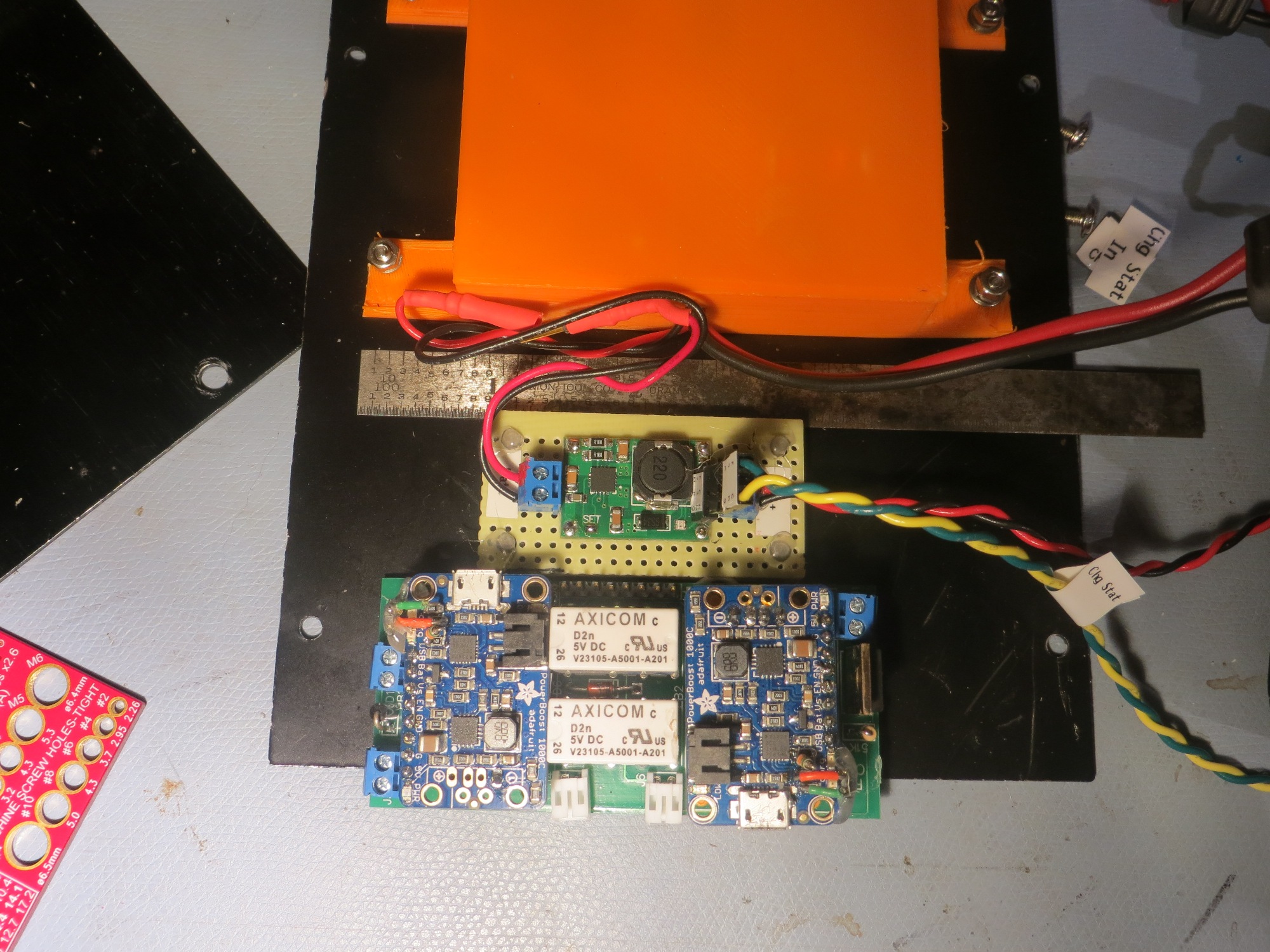
New TP5100-based charger module, with previous Adafruit PB1000C-based module below for size comparison. The orange box contains 4 Panasonic 18650 cells. Note the separate charge & load circuits
The following figures show the old and new schematics:
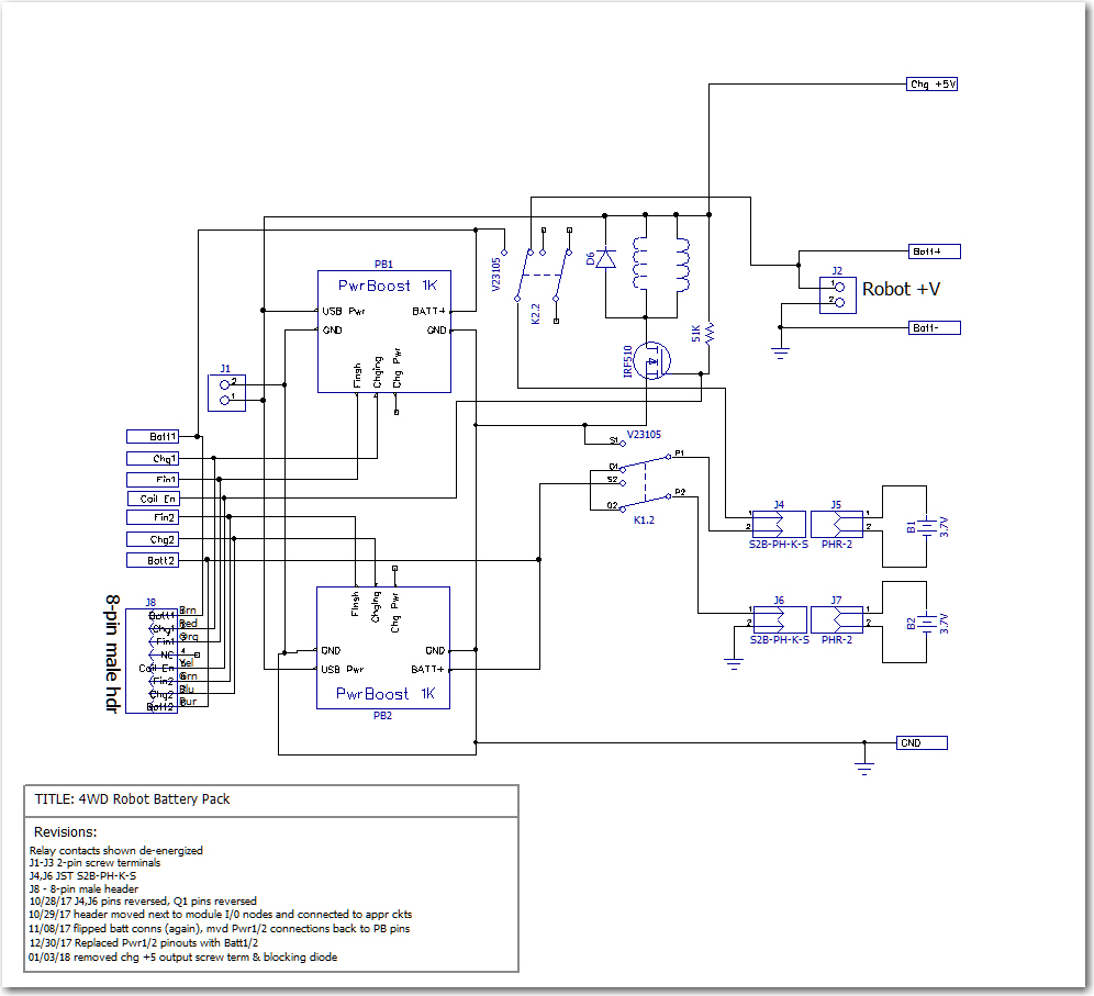
Old battery pack schematic
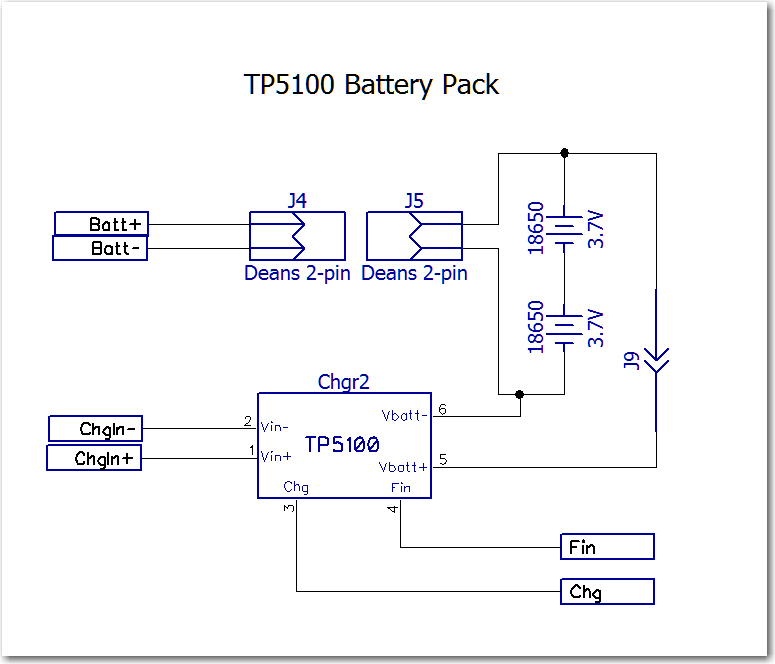
New battery pack schematic
Now that the load current doesn’t have to go through the charging module, I was able to replace all main battery wiring with #20 wire for lower IR drops, as shown below
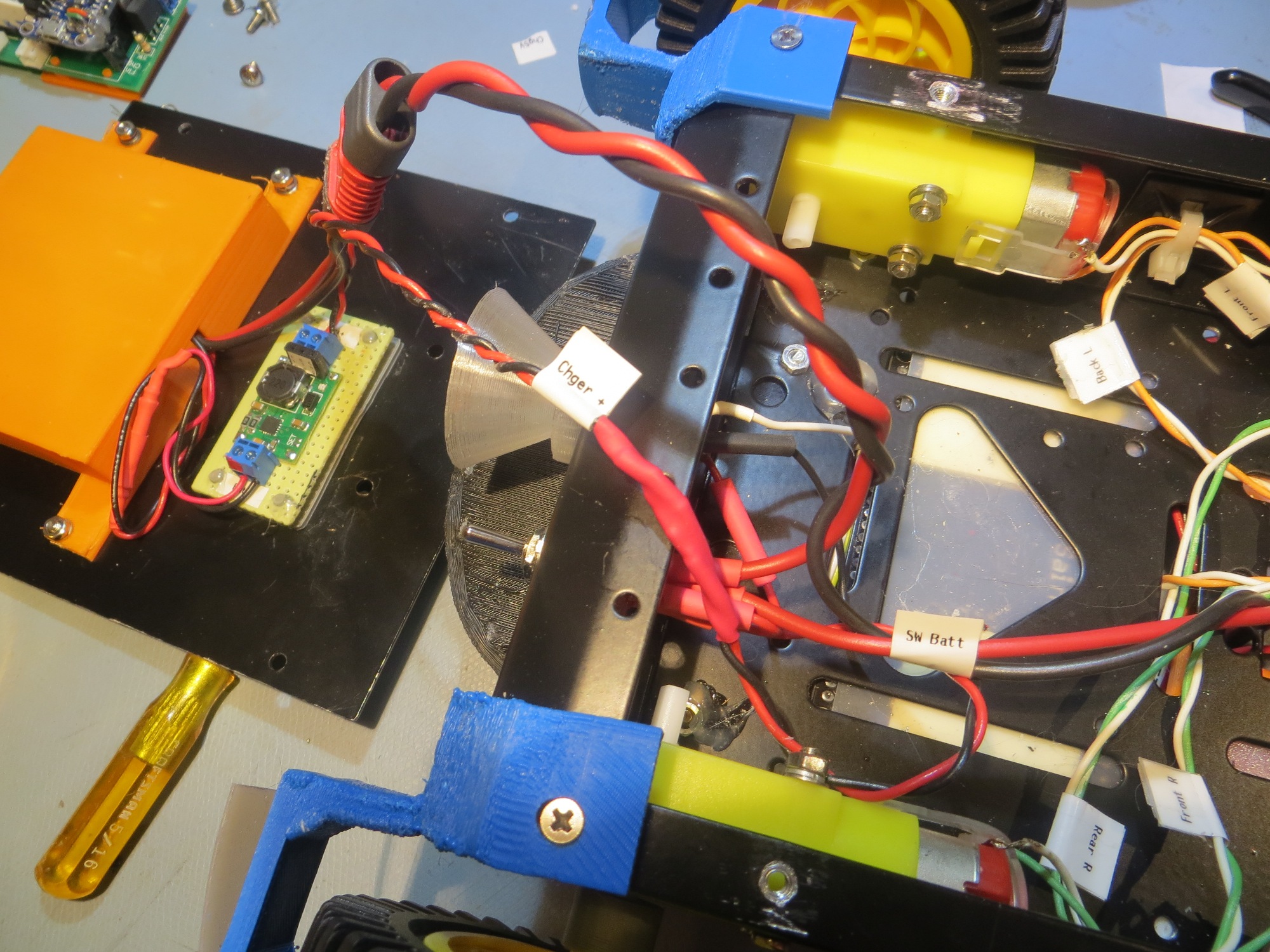
Power wiring replaced with #20 wiring, and 2-pin Deans connectors
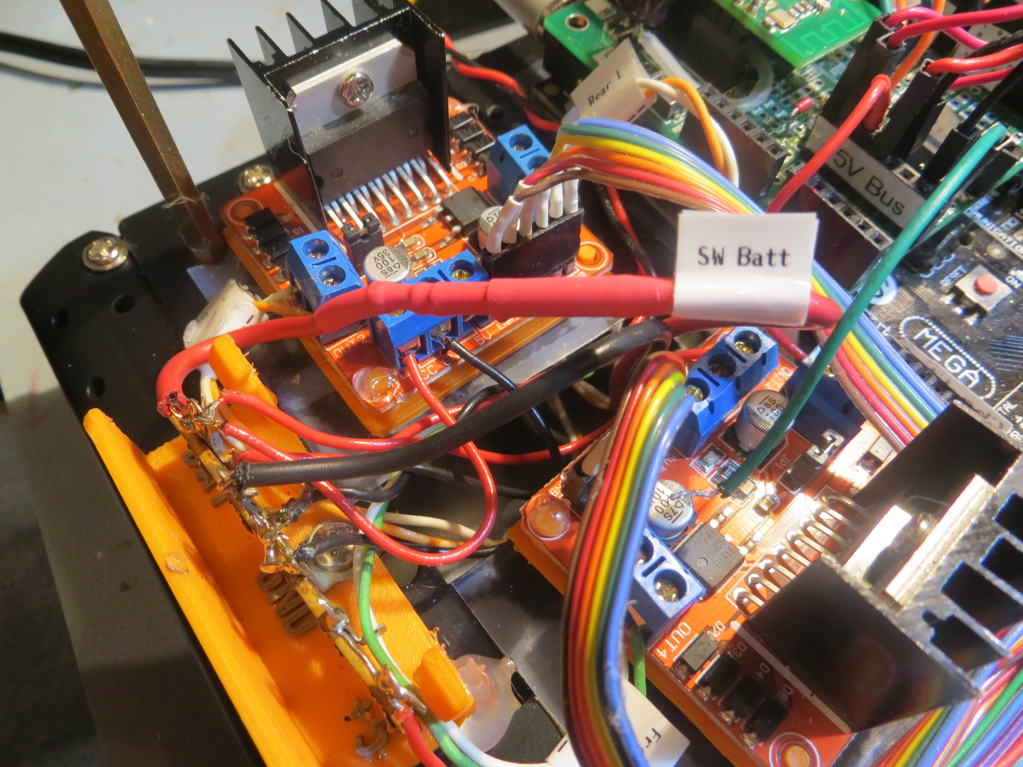
#20 wiring to main battery buss. Note in-line safety disconnect
The change to the new battery pack also considerably simplified the system hardware and software. The changes to the system schematic are shown below:
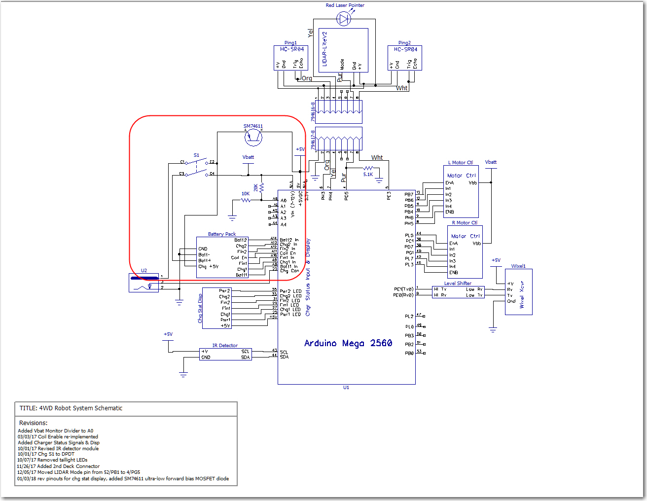
Old system schematic. Note the ultra-low-drop MOSFET diode required to keep Arduino Mega alive during charge. and the number of pins required for charge monitoring.
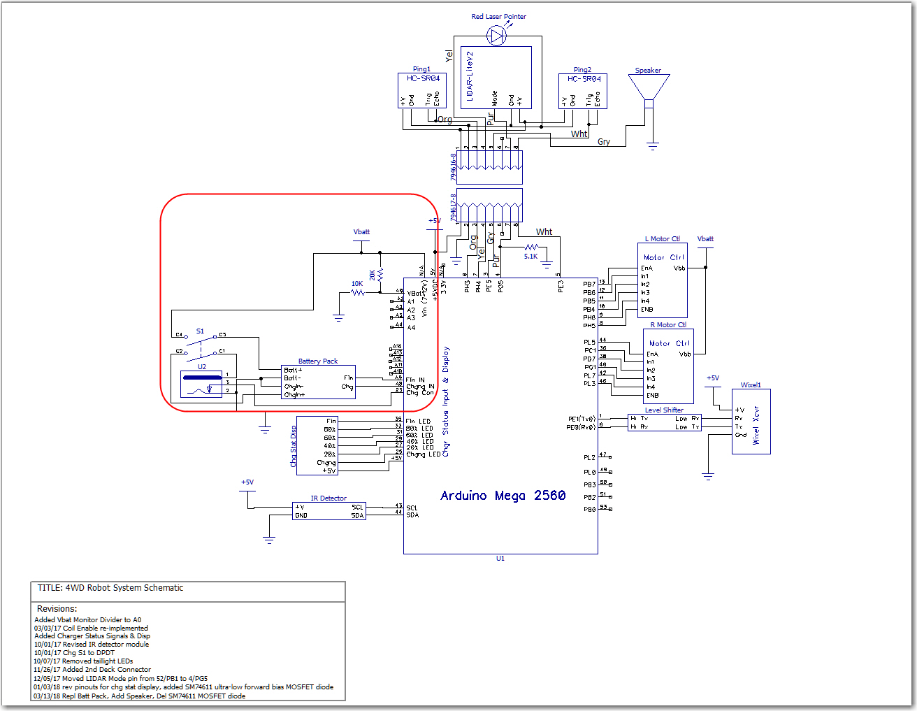
New system schematic. No requirement for diode, as full battery voltage is available at all times. Also, only two pins are required for charge monitoring
The operating system software has also been simplified. Now, instead of monitoring both cell voltages and four different status lines, only two lines have to be monitored. Also, there is now no requirement to correctly sequence the ‘Charger Connect’ and ‘Coil Enable signals in order to accomplish correct charging station connect-disconnect behavior. Now the system simply shuts off the motors when the robot connects to the station, and turns them back on again to disconnect. As an added benefit, the six charge status LEDs have been repurposed to show a crude approximation (based on battery voltage only for the moment) of charge status.
All these changes have caused one minor hiccup in the implementation of the charging station; the new charging voltage is +12V vs +5V as before. As you may recall, the charging station implements a square-wave modulated IR signal, and this signal is produced by a Teensy 3.2 and some associated circuitry, all of which expect +5V. This will require either a dual-output supply, or the addition of an on-board 12-to-5V regulator. This is still up in the air, but I suspect it will land on a simple 3-pin regulator.
So far, all the hardware changes (except for the charging station changes) have been accomplished, but the software changes have yet to be implemented and tested. Stay tuned!
Frank