Posted 27 August 2017
After returning from our eclipse-watching trip to our kids’ place in St. Louis (the solar eclipse was awesome, by the way), I spent some time rethinking the IR detector problem.
In St. Louis I was struck by how easy it was to overload the TLS267 sensors with either ambient sunlight or overhead incandescent lighting. The kitchen table where I was working had a hanging light with a halogen center bulb, and when that was on it immediately flooded the sensors, even with an ‘opaque’ sunshade; the only way I could get the sensors out of saturation was to hide it under an overturned coffee cup!
My friend and mentor John Jenkins’ solution for this was to add optical attenuation, such as a translucent film, but I wasn’t (and am not) sure this would work very well. And besides, it bothers me to have to work another problem (attenuator material selection, mechanical design, testing, etc) just to address a problem (too much gain, no gain control) with the TLS267 sensor part.
The TLS part is nice because it has a fairly wide beamwidth (so only 2 sensors are required) and its output is proportional to optical power density rather than inversely proportional like most phototransistors. However, its gain isn’t adjustable at all – you take what you get – thus the need for optical attenuation. Other parts, like the OSRAM SFH 300 (+/- 25deg) or 314 FA (+/- 40deg) have nice beamwidths, and the gain is adjustable via collector resistor selection.
- In the direct sunlight areas, the N-path filter completely solves the false positive problem, as the unmodulated sunlight signal won’t get through the filter, and I can allow the detectors to saturate without worrying about missing a charger station signal.
- In the indirect/no sunlight areas, I can’t allow the detectors to saturate, but since the maximum available field strength (at least from sunlight) is much lower (well below 0.1mA if you believe the 17 May data), then higher gain should still be OK.
- I plan to add some AGC capability by using multiple digital outputs to power the ptrans via multiple 12.5K resistors. I can 3-state outputs to disconnect them from the circuit, or drive them to Vcc to connect them. Each connected output would lower the gain. Two active outputs = 1/2 gain, 3 = 1/3, etc. That should take care of saturation issues near the charging station. The Teensy 3.2 has lots of digital outputs, so I could go wild along these lines if I wanted to ;-).
The above line of reasoning did not meet with approval from John; in fact it would be safe to say that I have driven him nearly to apoplexy with my blatant disregard for data that doesn’t support my thinking. Disregarding data is an absolute go-to-hell-and-burn-forever sin in John’s world (and in mine, to tell the truth), but I have a fair amount of confidence that the data he is referring to came out of a crappily-constructed experiment, while the data I am using to support my thinking came from a later much more rigorous one. When I’m dealing with John, I try to keep in mind that he is right about 90% of the time, so I have to have a ‘Plan B’ in the likely case that I’m wrong. In this particular case, ‘Plan B’ is simply to reduce the value of the collector resistor to the point where the sensor won’t saturate even in the face of my original crap-data experimental results. In the meantime, I can continue to enjoy tweaking John ;-).
Since I had some OSRAM SFH-300FA (+/-25 º beamwidth) phototransistors hanging around, I decided to try them in a 2-detector setup using a 30 º angle offset as shown in the images below:
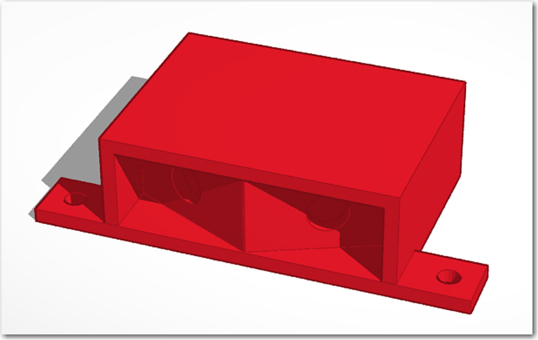
Rear view of SF300FA 2-detector mount design
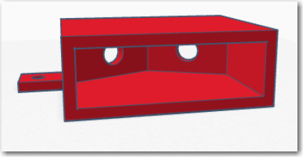
Front view of SF300FA 2-detector mount design
Front view of SF300FA 2-detector mount
Rear view of SF300FA 2-detector mount
For the initial trial, I used 10KΩ collector resistors as a starting point, mainly because I have lots of 10KΩ resistors, and zero 12.5KΩ ones.
When my grandson Danny and I were doing the azimuth scans of the TLS267 sensors in St. Louis, I realized that we needed lots more points than we were getting, if we were to have any hope of actually characterizing the azimuth response of the sensors, so I decided I was going to have to construct a computer-controlled azimuth scan turntable. I had a couple of cheap 28BYJ-48 stepper motors with an ULN2003-based driver (shown below), so I thought I might be able to rig something up.
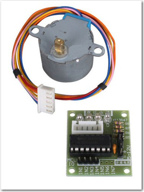
28BYJ-48 stepper motor with driver
Originally I had planned to integrate the turntable code directly into the IR Beacon Homing Module Arduino project, but I quickly realized this was a bad idea. Instead I created a new ‘RotaryScanner’ Arduino project to handle all the stepper motor related code, and then I created another Teensy-based project to actually perform the azimuth scan and record the results. To run a scan, I initialize the scan parameters (speed, start/stop angles, etc) using the RotaryScanner project, and trigger the scan from the recorder project. This way I get an azimuth scan where I know the start & stop angles associated with the data, and so I can interpolate the azimuth position for each datapoint – neat!
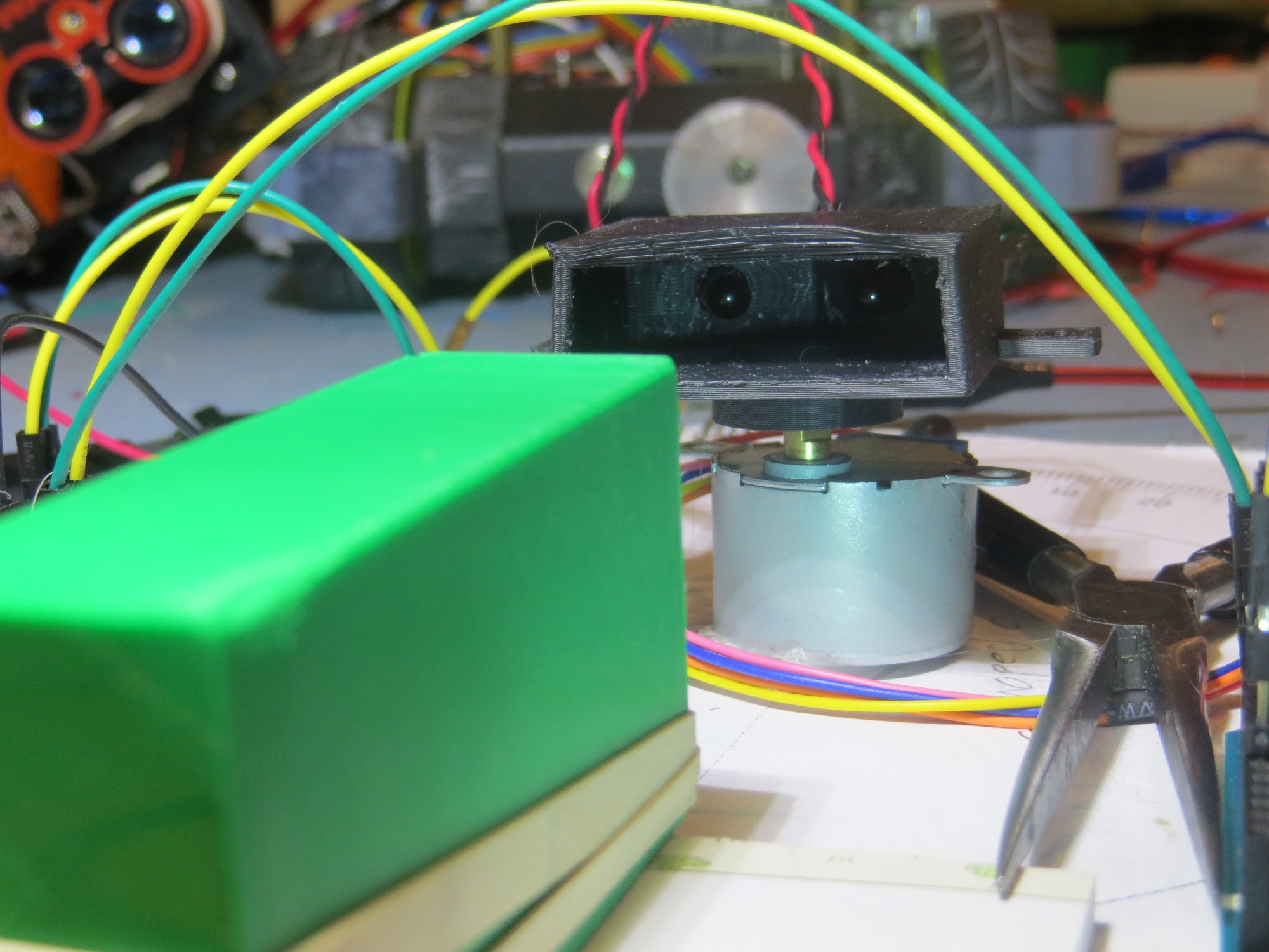
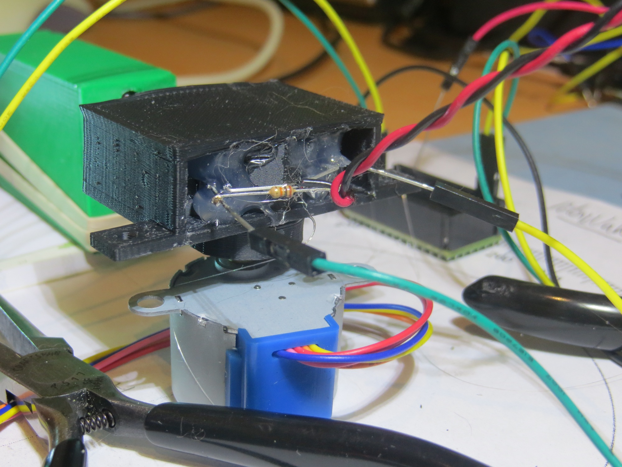
When I was finished with this little side project, I had a Uno-based RotaryScanner module interfaced to the stepper motor driver, and a Teensy-based recorder module to capture the sensor data. I also printed up a small turntable to adapt the sensor ‘sunshade’ module to the stepper motor shaft, proving once again how handy it is to have a 3D printer in my lab ;-). The entire arrangement is shown below, and I have included a short movie of the system in action.
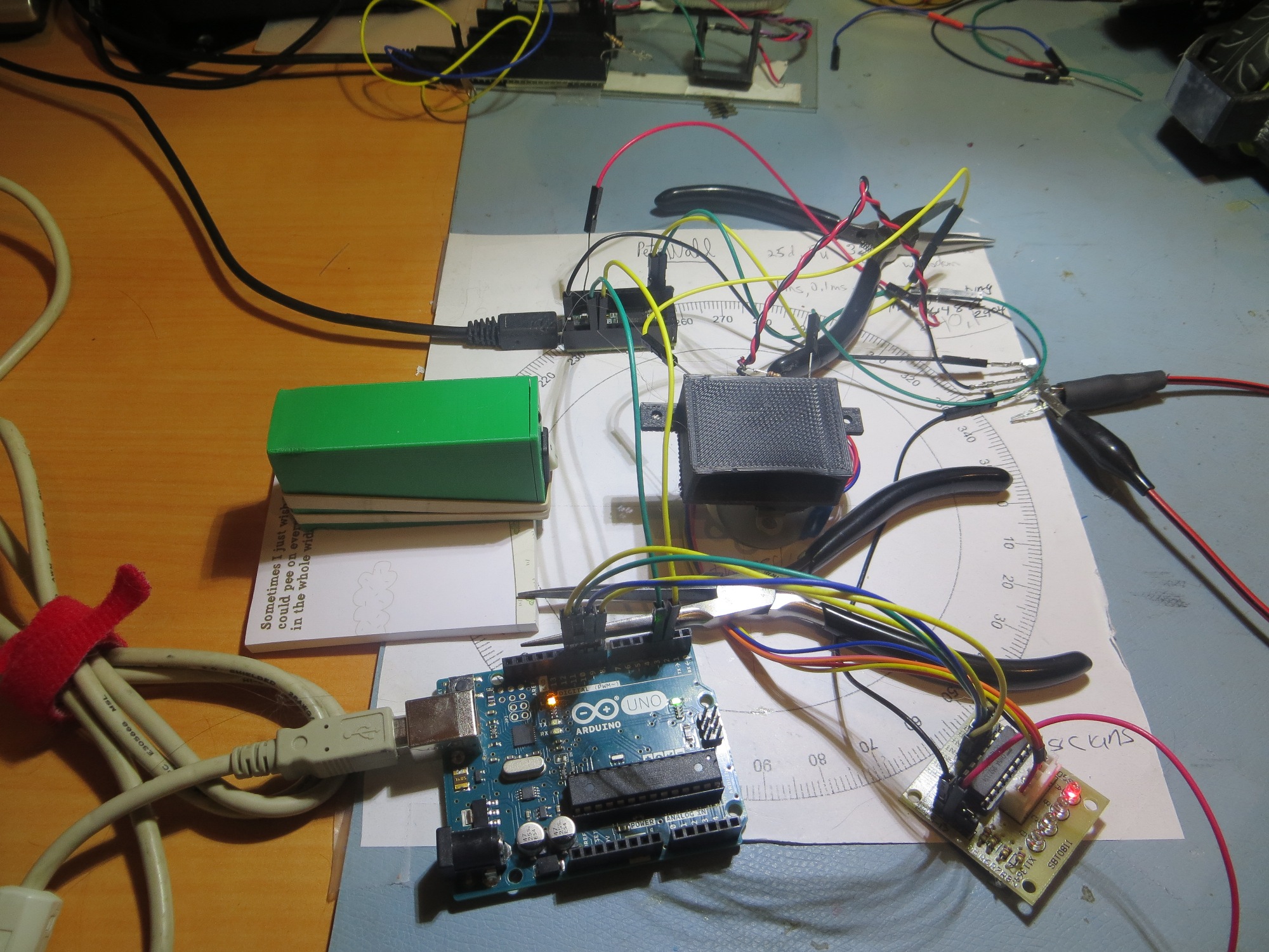
IR sensor azimuth scan setup. Uno stepper motor controller and motor driver are in the foreground, Teensy recorder module in the background. The IR sensor module is hot-glued to an adaptor disk, which mates with the stepper motor shaft. The stepper motor base is hot-glued to my compass rose sheet. The green box is my portable IR test source.
After getting everything set up and running, I collected an azimuth response data set using my portable IR source (the green box), with the results shown below
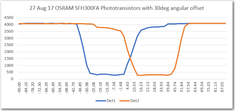
OSRAM SFH300FA phototransistors in a 30-deg offset arrangement, no center divider
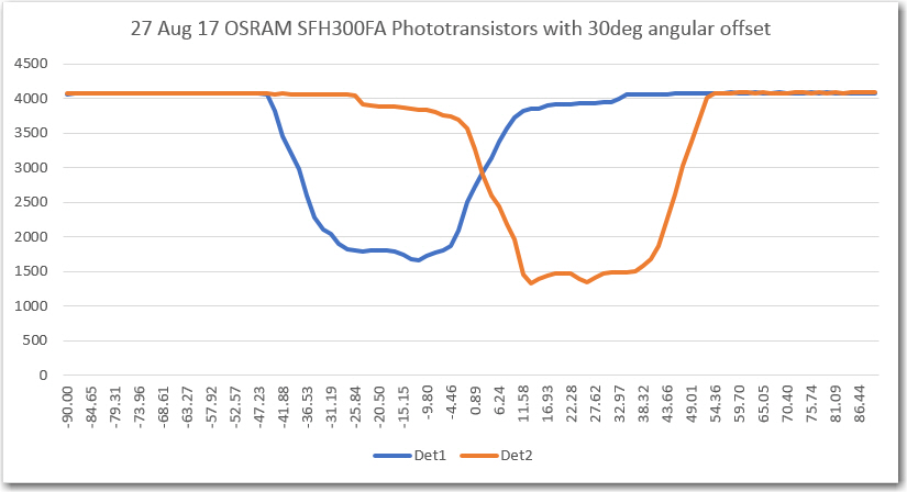
The horizontal axis values aren’t necessarily exact, as they are interpolated from the known starting and ending values, but they should be pretty close. As can be seen, there is pretty decent symmetry between the two responses. Unfortunately, both sensors saturated near their respective peaks. Here’s another plot with a slower rotation speed (more data points per degree), and with the IR source back a bit to get out of the saturation region
And here is a plot of the (Det1-Det2)/(Det1+Det2) steering function. From this plot, it appears that good steering information is availabale from about -27 º to about +36 º or about 63 º total. this might be a little narrow for the intended application, so the OSRAM S Stay tuned!
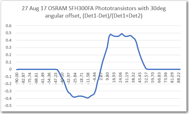
(Det1-Det2)/(Det1+Det2)
30 Aug 2017 Update:
I ran a couple more azimuth scans tonight, just playing verifying that I could get both forward and reverse scans to work.
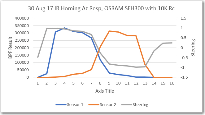
More detailed azimuth plot, using 2e OSRAM SFH-300s with Rc = 10k
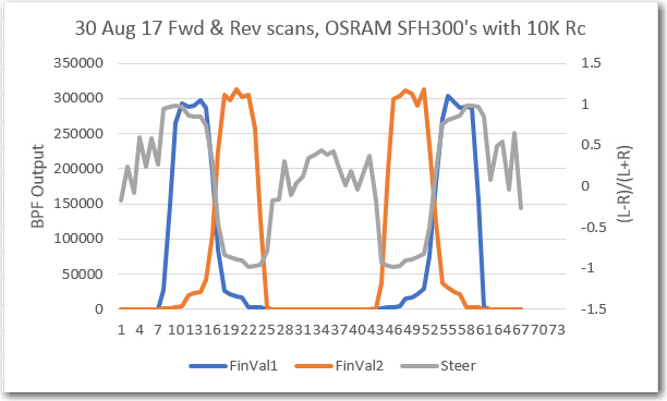
Forward and reverse azimuth plot, using 2e OSRAM SFH-300s with Rc = 10k
The next goal is to modify my Uno-based rotary scanner program to act as an IR source tracker, turning the stepper motor to keep the detectors aligned with an IR source. In the real robot, the detector module will be fixed, and the the wheel motor speeds will be adjusted to center the entire robot on the IR source. However, I believe I can test out the algorithm without having to fully integrate the module onto the robot. Stay tuned!
Frank