
Posted March 14, 2016
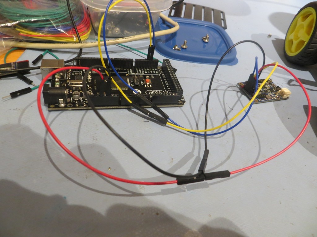
In my last post from about a week ago, I described my ongoing efforts to integrate the CK Devices Mongoose 9DOF IMU into my ‘Wall-E2’ wall-following robot. Since that time, I have gotten the Mongoose successfully integrated into the robot, and am able to see magnetometer & accelerometer readings being passed through the host Arduino Mega to the PC via the Mega’s serial port.
After getting all the hardware and software issues worked out, I have now started on the issue of getting the magnetometer calibrated for it’s new home in the robot. All magnetometers need to be calibrated after installation to compensate for errors caused by nearby metal (ferrous and non-ferrous) objects; otherwise the reported magnetic heading can be substantially off. I have considered just using a 360-element lookup table containing offset values, but that’s a bit tacky even for one with my low standards, so I have been researching available magnetometer calibration techniques and tools. I found a nice discussion at DIY Drones here, but I have been having trouble getting the tools to work. The discussion (and tools) center around the widely available GY-273 HMC5883L breakout board, and this ain’t quite the same animal as the Mongoose.
Following the general line of the discussion at DIY Drones, I downloaded the ‘MagMaster’ ZIP files, and attempted to get the MagViewer visualizer program linked up with my Mega/Mongoose combination, without much success. After flailing around for a while with the robot/Mongoose setup, I decided to simplify things by isolating the Mega/Mongoose combination from everything else going on with the robot. I had a spare Mega, so I simply connected the Mongoose to Tx1/Rx1 on the spare (same as on the robot) and loaded a modified version of the robot controller onto the Mega.
The modifications basically stripped away everything to do with the robot, leaving only the code that interfaces with the Mongoose. According to the DIY Drones discussion, this should have allowed the MagViewer program to see the same magnetometer data as for the GY-273, but apparently not. The viewer program never shows any activity – bummer!
Posted March 16, 2016
Well, I’m still not sure why the MagViewer program didn’t recognize the Mongoose mag data (I posted to the DIY Drones forum, but no replies yet), so I decided I would try a variant on my original idea of a lookup table.
First, I needed a way to accurately orient my Mongoose module to different headings. I Googled around a bit, and found a protractor printing site that offered 360-degree heading graphics like the one shown below
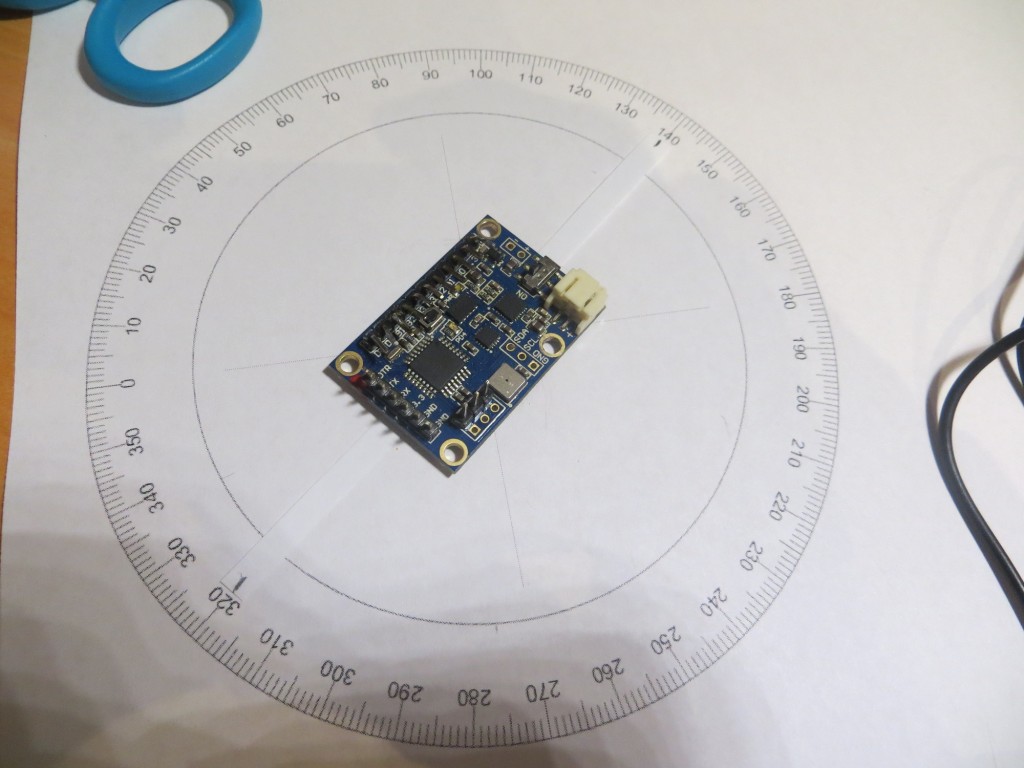
4-inch heading circle, calibrated in degrees
Then I taped a narrow strip of paper to the bottom centerline of the Mongoose module to make an accurate pointer, and proceeded to record the actual Mongoose heading reading for each 5-degree increment around the circle. I started this process by orienting the paper heading circle so that the 0/360 point corresponded to a Mongoose heading reading of 0 degrees, i.e. aligned with magnetic north as measured by the Mongoose. The data were recorded in an Excel spreadsheet, and the error term (difference between the nominal heading value and the Mongoose reading) was calculated and graphed, as shown below.
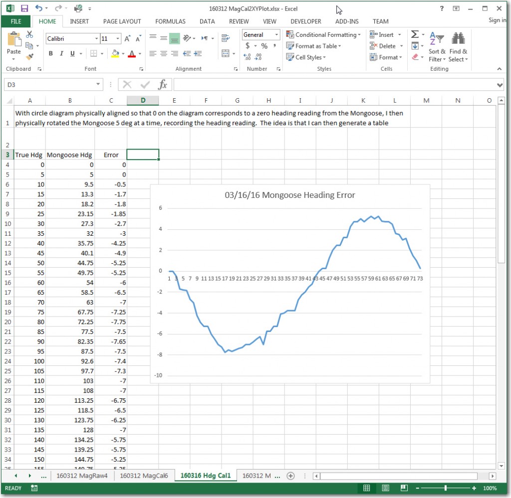
Mongoose reading versus actual magnetic heading, with error plot
Well, when the graph first popped up, I just about fell off my chair, as I recognized an almost perfect sine wave graph. This immediately told me two things:
- The Mongoose sensor, the test setup and the data was all valid. There is no way I could have managed that smooth of a curve by accident, and also no way it could have been that smooth if there was any significant mag field distortion
- At least for this case, with no significant installation errors, almost perfect heading compensation could be accomplished with just a simple sine function with a slight negative DC offset corresponding to the average value of all errors (about -1.35 according to Excel)
To test this theory, I used Excel to calculate the required sin function values, and added the result to the calculated error values for each measured angle. Then I plotted the compensation and comp+error curves on the same plot as before, as shown below.
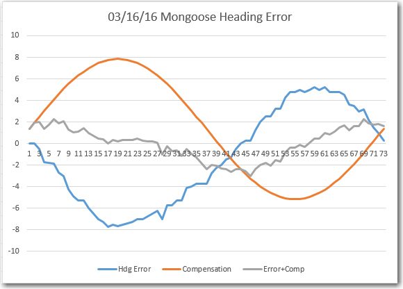
Angle Error, Comp values, and Comp+Error
From the plot, it is clear that the compensation is effective, although not perfect. The compensated error amplitude looks to be about 2-2.5 degrees, more than adequate for my purposes. I think the remaining error is due to the fact that the sensor data traces out an ellipse rather than a circle.
So, the next step is to install the Mongoose sensor back on the robot, and do a similar test utilizing an 8″ diameter version of the heading graphic. Assuming I get similar compensation results, I’ll probably call it a day and start running field tests. After all, I’m not sure I care if Wall-E thinks a hallway is oriented at 270, 260, or 280 degrees magnetic, as long as the next time it goes down the same hallway it gets more or less the same results!
Stay tuned!
Frank