Posted 20 April, 2016
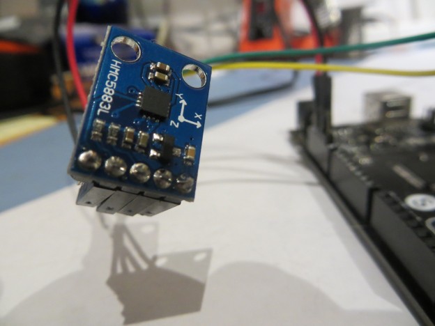
I have been trying to add a magnetometer to my Wall-E2 robot for a while now, and have been plagued by installation-induced errors. A magnetometer works fine on the bench in isolation, but not when installed on the robot. So far, I have determined that the DC drive motors are a big contributor to these errors, and the only way to address this is with magnetometer calibration. At first I tried just a simple lookup-table based approach, since I only needed to correct for azimuth errors (my wheeled robot very rarely departs from a horizontal orientation). Again, this worked great ‘on the bench’, but failed miserably in the installed configuration.
So, after being forcibly convinced that ‘the easy way’ wasn’t going to work, I began researching magnetometer calibration techniques and tools. At the DIY Drones website, I found a very informative article by Yury Matselenak with a great explanation, and a set of two tools (a visualizer and a calibration tool). I thought I was ‘in like Flynn’ and downloaded the tools. Unfortunately the visualizer tool didn’t recognize comm two-digit port port numbers, so once again I was stuck (Yuri later gave me a link to the visualizer source code, but I haven’t yet had the time to fix it for the higher numbered ports). In the meantime, I found another calibration tool, written in MATLAB by Alain Barraud, so I decided to try my hand at a magnetometer calibration manager. I have a fair bit of experience with MATLAB from a prior lifetime as a researcher, and I have previously ported MATLAB code to C++, so how hard could it be? From a previous project I had access to an older version the neat EyeShot 3D visualization libraries, so it was easy to add a 3D viewport to a standard C# Windows form. My plan was to have a ‘raw’ and a ‘calibrated’ view, so it would be easy to see the effects of the calibration process, and to use the free MathNet.Numerics matrix manipulation tools to port the MATLAB code. Unfortunately, the MATLAB matrix manipulation routines used in the calibration code didn’t correspond closely enough to MathNet’s library functions, so I got stuck during the port and wasn’t able to finish the ‘calibrated’ side of the application – bummer!
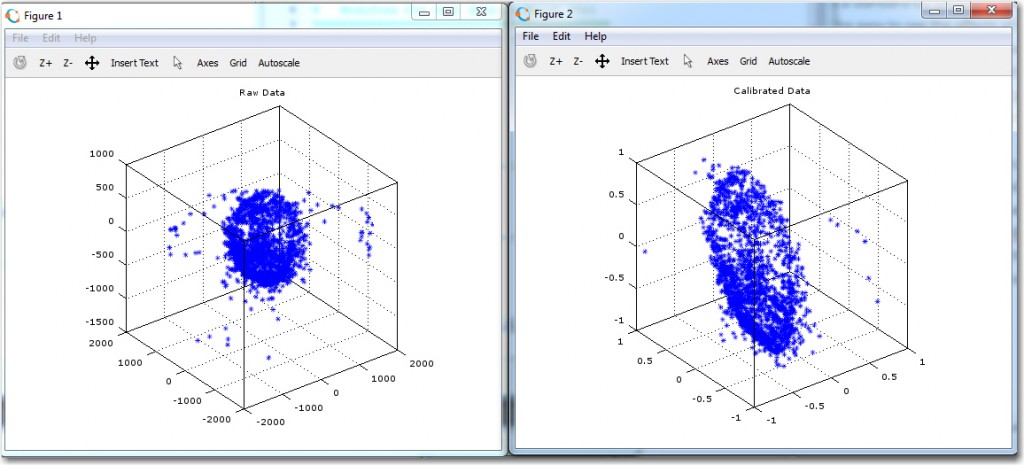
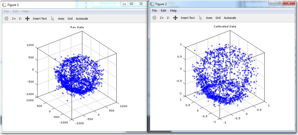
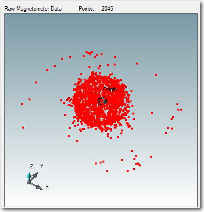
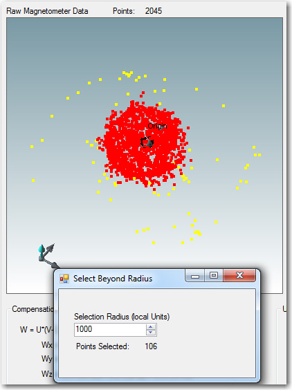
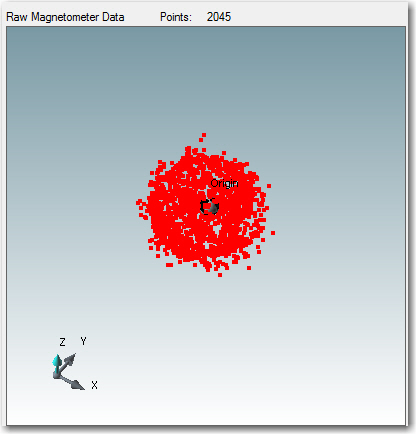
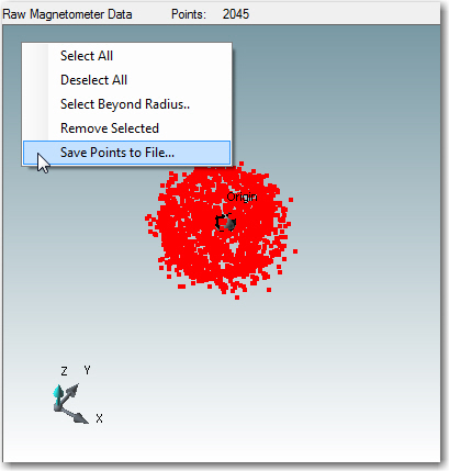
However, I did get far enough along to notice another problem; the raw data from my magnetometer exhibited a lot of ‘spread’ in one of the principal planes, where a small percentage of the data points formed a rough circle at about twice the radius as all the other points. When I ran this dataset through Alain’s original MATLAB code (using Octave on my Linux box) the ‘calibrated’ dataset actually looked worse than the original. This prompted me to add some point editing capability to my visualizer, so I could visually remove ‘outrider’ data prior to attempting calibration.
Here are some shots of the process of pruning the dataset using my calibration app
So, even though I couldn’t (and still can’t) figure out how to port Alain’s MATLAB code into my calibration tool, I was able to use the tool to visually prune outliers from my data prior to running it through the calibration routine, and so all my work wasn’t a complete waste – whoopee! (not).
Frank
Pingback: Magnetometer Calibration, Part II - Paynter's Palace
Pingback: Giving Wall-E2 A Sense of Direction, Part IX - Paynter's Palace
Pingback: Time and Memory for Wall-E2 - Paynter's Palace